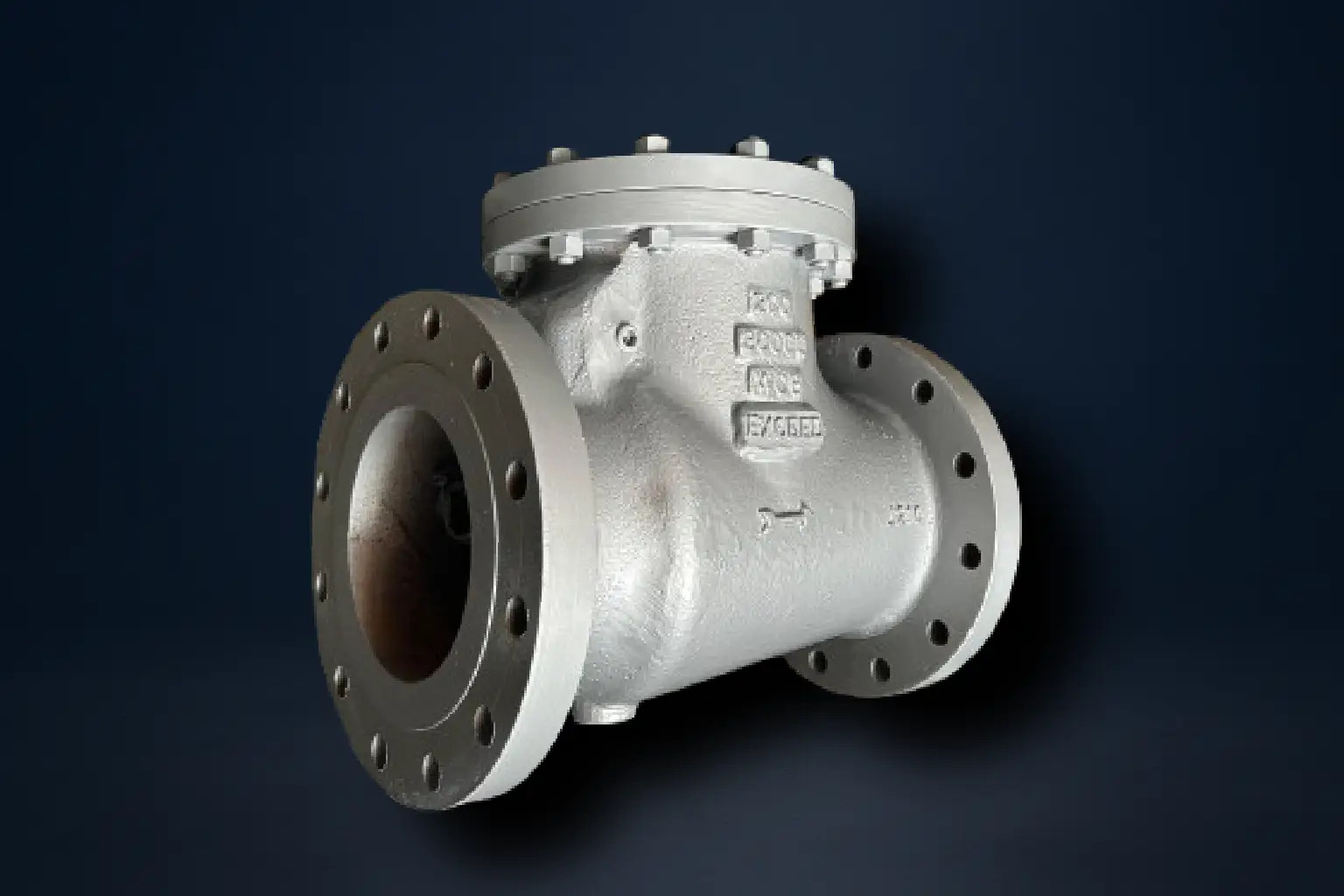
Swing Check Valves

Service Image

Swing Check Valves

Swing check valves are unidirectional valves designed to stop reverse flow in pipelines, ensuring that fluid moves only in the intended direction. They are widely used in systems where backflow could damage equipment, contaminate fluid lines, or cause safety hazards. The valve operates using a swinging disc attached to a hinge or shaft. When the fluid flows forward, the disc swings away from the seat, allowing an unobstructed path. When the flow stops or reverses, the disc returns to the seat, creating a seal that blocks reverse movement.

Because of their automatic operation, swing check valves do not require an operator or actuator. This makes them highly reliable in continuous and remote applications such as water distribution, process piping, and pump discharge lines. Their simple, rugged design ensures a long service life with minimal maintenance, making them one of the most widely used types of check valves.

Exceed manufactures swing check valves with a focus on precision sealing, durability, and low pressure loss. By combining robust body construction with carefully engineered disc-seat geometry, Exceed valves deliver reliable protection against backflow across a wide range of applications.


Technical Details:

Manufacturing Std.: BS 1873

Testing & Inspection Std.: API 598

Face to Face: As per ASME B16.10

End Connections: Flanged as per ASME B16.5 RF


Engineering Options:

  • Special materials available on request
  • Remote operation on request

The working principle of a swing check valve is based on the movement of the disc in response to flow pressure:

  1. Forward Flow (Open Position):
    When fluid enters the valve in the forward direction, the pressure pushes the disc away from the seat. The disc swings upward on its hinge, allowing flow to pass with minimal obstruction. The design of the body and disc ensures that the pressure drop across the valve is low, keeping the system efficient.

  2. No Flow (Neutral Position):
    If forward flow reduces or stops, the disc gradually returns toward the seat. The combination of gravity and the weight of the disc positions it close to closing, ready to respond if backflow begins.

  3. Reverse Flow (Closed Position):
    If flow reverses, backpressure forces the disc tightly against the seat. This creates a seal that prevents reverse movement of fluid. A properly designed swing check valve closes quickly enough to protect equipment like pumps from damage while avoiding water hammer by ensuring smooth disc movement.

This automatic operation makes swing check valves particularly effective in protecting pumps, compressors, and storage systems, as they shut off flow without requiring manual action or external power.

Swing check valves are commonly used:

  • At pump outlets – to prevent reverse flow when pumps shut down.

  • In water supply lines – to stop contaminated or stagnant water from flowing back into clean lines.

  • In process systems – to safeguard heat exchangers, compressors, and storage tanks from reverse pressure.

  • In fire protection systems – to ensure reliable one-way flow in sprinkler and hydrant systems.

  • Automatic Backflow Prevention
    Swing check valves operate automatically without external intervention.
    Exceed ensures precise seat-disc alignment for dependable sealing and reduced leakage risk.

  • Simple, Robust Design
    With only a few moving parts, swing check valves require minimal maintenance and provide long service life.
    Exceed machines its valves to close tolerances and uses quality materials for durability and wear resistance.

  • Low Pressure Drop
    The swinging disc design allows smooth, unobstructed forward flow.
    Exceed optimizes disc geometry to minimize flow resistance and energy loss.

  • Versatile Use
    Suitable for a wide range of fluids including water, steam, oil, and chemicals.
    Exceed offers material and seat options tailored for demanding applications.

No Parts Name Qty. Materials
1 Lever Arm `1 ASTM A 216 Gr. WCB
ASTM A 351 CF8/CF8M/CN7M
2 Arm Nut C.S
S.S.304/316
3 Disc 1 C.S with 13% Cr

S.S304/316

4 Seat Ring 1 S.S 13% Cr.

Integral Seat for Alloy Seat Valve

5 Arm Pin 1 AISI 410/304/316
6 Bracket 1 ASTM A216 Gr. WCB

ASTM A351 Gr. CF8/CF8M/CN7M

7 Body 1 ASTM A216 Gr. WCB

ASTM A351 Gr. CF8/CF8M/CN7M

8 Body Seal 1 Compressed Asbestos Fibre
9 Stud & Nut Reqd. ASTM 193 Gr. B7

ASTM 194 Gr. 2H

10 Cover Plate 1 ASTM A216 Gr. WCB

ASTM A351 Gr. CF8/CF8M/CN7M


Material Class Working Pressure @ 38°C Temp. Hyd. Test Pressure (Body) Hyd. Test Pressure (Seat)
WCB 150

300


600

19.6 bar


51.1 bar


102.1 bar

425°C

29.4 bar


76.7 bar


153.2 bar

21.6 bar


56.2 bar


112.3 bar

CF8/CF8M 150

300


600

19 bar


49.6 bar


99.3 bar

425°C

28.5 bar


74.4 bar


149 bar

20.9 bar


54.6 bar


109.2 bar

CN7M 150

300


600

15.9 bar

41.4 bar


82.7 bar

325°C 23.9 bar

62.1 bar


124 bar

17.5 bar

45.5 bar


91 bar

Important Notes:

1) Temprature shown is the maximum service temprature of the valve. The allowable working pressure decreases as temprature increases. Always refer to the ASME B16.34 pressure-temprature ratings for the exact value at the required temprature.

4) Hydrostatic test pressures are based on API 598 requirements:

  • Body (shell) test = 1.5 x rated working pressure
  • Seat (closure) test = 1.1 x rated working pressure
Size NB. A
25 127
40 165
50 203
65 216
80 241
100 292
125 330
150 356
200 495
250 622
300 698


Size NB. A
25 203
40 241
50 267
65 292
80 318
100 356
125 400
150 444
200 533
250 622
300 711


(Dimensions above 300mm available on request)

*All dimensions are in mm

Size NB. A
25 216
40 241
50 292
65 330
80 356
100 432
125 508
150 559
200 660
250 787
300 838


(Dimensions above 300mm available on request)

*All dimensions are in mm