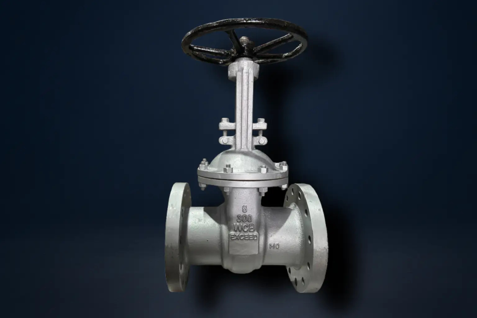
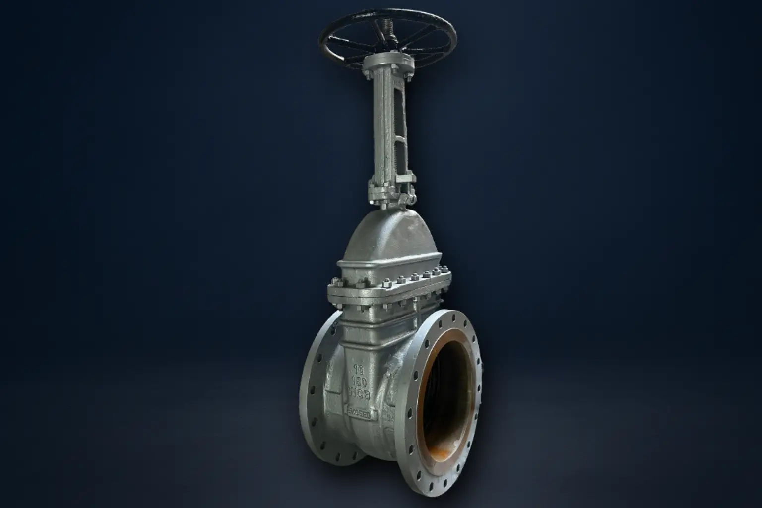
Gate Valves

Service Image
Service Image

Gate Valves

Gate valves are primarily designed for on/off service, providing a straight-through flow path with minimal resistance when fully open. Unlike globe valves, which are ideal for throttling, gate valves are best suited for applications where a full flow or complete isolation is required.

The key feature of a gate valve is its wedge-shaped disc (gate), which moves linearly along the flow path to either block or allow fluid. This design ensures low pressure drop and high flow efficiency when the valve is fully open. Gate valves are widely used in pipelines carrying liquid, gas, or slurry, where long-term durability and reliable isolation are critical.

At Exceed, our gate valves are engineered with robust materials, precision-machined components, and high-integrity seating surfaces, ensuring smooth operation, tight shut-off, and long service life even under demanding operating conditions. Our valves feature flexible wedge designs, which provide improved sealing performance and better adaptability to temperature changes.

Gate valves operate using a wedge-shaped disc (gate) that moves perpendicular to the flow. Turning the handwheel or actuator raises or lowers the gate:

  • Fully Open – The gate is completely lifted out of the flow path, allowing unrestricted flow with minimal pressure drop.

  • Fully Closed – The gate is lowered onto the seat, completely isolating the flow.

  • Intermediate Positions – Gate valves are not recommended for throttling, as partial opening can cause vibration, wear, and erosion of the gate and seat.

Design features that make gate valves effective for isolation:

  • Straight-through flow reduces pressure drop and turbulence

  • Guided gate movement ensures smooth operation and accurate sealing

  • Multiple gate designs (solid wedge, flexible wedge, parallel) can be chosen based on application requirements

Gate valves are selected for applications where full flow or complete shut-off is required:

  • Water and wastewater pipelines – Provide reliable isolation for maintenance and system control

  • Oil and gas transmission – Offer minimal flow resistance and can handle high pressure

  • Steam pipelines – Used in combination with safety devices to isolate sections of the system

  • Chemical and process lines – Provide dependable shut-off in critical piping networks

  • Fire protection systems – Ensure full flow and isolation when required

  • Low Flow Resistance
    Gate valves offer straight-through flow when fully open, minimizing pressure drop.
    Exceed ensures precision machining for smooth flow and minimal turbulence.

  • Reliable Shut-Off
    The wedge gate provides complete isolation of the line when closed.
    Exceed designs gates and seats for tight sealing, reducing the risk of leaks.

  • Durable Construction
    Gate valves are built to withstand high pressure and temperature cycles.
    Exceed uses high-grade materials and robust body designs for long-lasting performance.

  • Smooth Operation
    Well-guided gate movement reduces operational effort and wear.
    Exceed optimizes stem and gate alignment to ensure smooth operation and longer valve life.

  • Enhanced Sealing with Flexible Wedge
    Flexible wedge designs improve the valve’s ability to adapt to thermal expansion and maintain reliable sealing, providing superior performance in varying operating conditions.
    Exceed incorporates flexible wedge design in all its gate valves to enhance sealing reliability and long-term durability.

No Parts Name Qty. Materials
1 Body 1 ASTM A216 Gr. WCB
2 Seat Rings 2 S.S. 13% Cr.
3 Wedge 1 IC S.S. 410
4 Spindle 1 S.S AISI 410
5 Bonnet 1 ASTM A216 Gr. WCB
6 Gasket 1 Spiral wound metallic gasket
7 Bonnet Stud & Nut Reqd. ASTM A 193 Gr. B7/ASTM A193 Gr. 2H/ M.S.
8 Bonnet Bush 1 S.G Iron
9 Gland Packing 6 min Graphited
10 Gland Follower 1 S.G. Iron
11 Yoke Bush 1 G.M. / S.G Iron
12 Cross Bolt & Nut 2/2 Carbon Steel / M.S
13 Eye Bolt & Nut 2/2 Carbon Steel/ M.S.
14 Grub Screw 1 Carbon Steel / M.S.
15 Hand Wheel 1 S.G. Iron
16 Wheel Nut 1 S.G Iron
17 Name Plate 1 Alluminium


Material Class Working Pressure @ 38°C Temp. Hyd. Test Pressure (Body) Hyd. Test Pressure (Seat)
WCB

150


300

19.6 bar


51.1 bar

400°C

29.4 bar


76.7 bar

21.6 bar


56.2 bar

CF8/CF8M

150


300

19 bar


49.6 bar

400°C

28.5 bar


74.4 bar

20.9 bar


54.6 bar

Important Notes:

1) Temprature shown is the maximum service temprature of the valve. The allowable working pressure decreases as temprature increases. Always refer to the ASME B16.34 pressure-temprature ratings for the exact value at the required temprature.

4) Hydrostatic test pressures are based on API 598 requirements:

  • Body (shell) test = 1.5 x rated working pressure
  • Seat (closure) test = 1.1 x rated working pressure
Size NB. A B C D E F G
25 127 51 14 108 4 79 16
40 165 73 14 127 4 98 16
50 178 92 16 152 4 121 19
65 190 105 17 178 4 140 19
80 203 127 19 190 4 152 19
100 229 157 24 229 8 190 19
125 254 186 24 254 8 216 22
150 267 216 25 278 8 241 22
200 292 270 29 343 8 298 22
250 330 324 30 406 12 362 25
300 356 381 32 483 12 431 25
350 413 35 534 12 477 29 29
400 406 470 37 597 16 540 29

(Dimensions above 400mm are available on request)

*All dimensions are in mm

Size NB. A B C D E F G
40 191 73 21 156 4 114 22
50 216 92 22 165 8 127 22
65 241 105 25 190 8 149 22
80 282 127 29 209 8 168 22
100 305 157 32 254 8 200 22
125 381 186 35 279 8 235 22
150 403 216 37 318 12 270 22
200 419 270 41 381 12 330 25
250 457 324 48 445 16 387 29
300 502 381 51 521 16 451 32
350 762 413 54 585 20 515 32
400 838 470 58 648 20 572 35

(Dimensions above 400mm are available on request)

*All dimensions are in mm