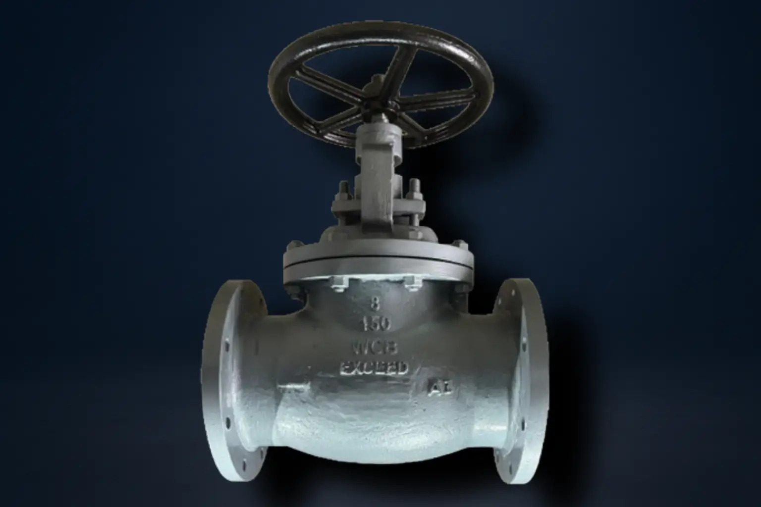
Globe Valves

Service Image

Globe Valves

Globe valves are one of the most reliable and widely used valve types for throttling and regulating flow in pipelines. Their design is fundamentally different from gate or ball valves, which are primarily intended for isolation (fully open or fully closed service). In a globe valve, the disc moves perpendicular to the flow, which creates a gradual change in flow area as the valve opens or closes. This makes them ideal anywhere precise control, stable operation, or controlled pressure drop is needed.

Globe valves are especially suited for systems where flow rate must be adjusted frequently, where sudden surges could damage downstream equipment, or where tight shut-off is required even after repeated operation. They offer better flow control accuracy than most other valve types, which is why they are commonly found in control stations, dosing lines, and recirculation systems.

At Exceed, we design our globe valves to maximize these inherent strengths. Every valve is built with precision-machined internals for smooth throttling, high-integrity sealing surfaces for reliable shut-off, and rugged construction to withstand demanding operating conditions. This ensures our valves deliver long-term, consistent performance while reducing the total cost of ownership for your plant.


Technical Data:

Manufacturing Std.: BS 1873

Testing & Inspection Std.: API 598

Face to Face: As per ASME B16.10

End Connections: Flanged as per ASME B16.5


Engineering Options:

  • Available on request with gearbox, electric actuator or pneumatic actuator
  • Special materials available on request
  • Remote operations on request

Globe valves control the flow of fluids by using a movable disc and a stationary ring seat inside a spherical body. When the handwheel or actuator is turned, the stem moves the disc vertically towards or away from the seat.

As the disc approaches the seat, the flow area narrows, which increases resistance and reduces flow. This linear flow characteristic allows operators to make small, precise adjustments to the flow rate.

Key design aspects that make globe valves suitable for control:

  • Shorter travel between open and closed positions — allows quicker response.

  • Well-guided disc and stem — prevents vibration and ensures smooth movement.

  • Flow path changes direction inside the body — increases pressure drop, which actually helps in throttling and pressure control.

  • Available in different seat and disc designs (plug type, needle type, parabolic) to suit various control needs.

Because of this design, globe valves are ideal anywhere gradual, accurate flow control is needed instead of just fully open/closed operation.

  • Steam and condensate lines – Allow controlled opening to prevent water hammer and thermal shock.

  • Cooling and heating loops – Help balance flow for precise temperature control across multiple branches.

  • Dosing or fuel lines – Provide accurate control where small changes in flow can affect the process outcome.

  • Pump bypass lines – Maintain a minimum flow to protect pumps from running dry or overheating.

  • Control stations – Gradually reduce pressure to protect downstream equipment from sudden surges.

  • Excellent Throttling Capability
    Globe valves allow fine flow regulation.
    Exceed uses precision-machined seating surfaces to keep throttling consistent over long-term use.

  • Tight Shut-Off
    The disc presses squarely onto the seat to block flow completely.
    Exceed ensures accurate alignment of the disc and seat for reliable sealing.

  • Durability in Demanding Conditions
    Globe valves can handle high pressure and temperature cycles.
    Exceed builds valves from certified materials and robust stem-disc designs to resist wear and thermal stress.

  • Ease of Operation
    Smooth stem threads and guided movement make globe valves easier to operate.
    Exceed optimizes stem design to lower operating torque and extend actuator life.

No Parts Name Qty Materials
1 Body 1 ASTM A 216 Gr. WCB
ASTM A 351 CF8/CF8M/CN7M
2 Seat 1 AISI - 410
3 Plug 1 AISI - 410
Back Seat 1 AISI - 410
Gland Packing   Graphited
6 Spindle 1 AISI -410
7 Gland Follower 1 S.G Iron
8 Bonnet 1 IS 210 Gr. 220, ASTM A 216 Gr. WCB, ASTM A 351 CF8/CF8M/CN7M
9 Yoke Bush 1 S.G Iron
10 Hand Wheel 1 S.G Iron
11 Stud/Nut Req ASTM A 193 Gr.B7/ASTM A 194 Gr. 2H/M.S.


Material Class Working Pressure @ 38°C Temp. Hyd. Test Pressure (Body) Hyd. Test Pressure (Seat)
WCB

150


300

19.6 bar


51.1 bar

400°C

29.4 bar


76.7 bar

21.6 bar


56.2 bar

CF8/CF8M

150


300

19 bar


49.6 bar

400°C

28.5 bar


74.4 bar

20.9 bar


54.6 bar

CN7M

150


300

15.9 bar


41.4 bar

325°C

23.9 bar


62.1 bar

17.5 bar


45.5 bar

Important Notes:

1) Temprature shown is the maximum service temprature of the valve. The allowable working pressure decreases as temprature increases. Always refer to the ASME B16.34 pressure-temprature ratings for the exact value at the required temprature.

2) Hydrostatic test pressures are based on API 598 requirements:

  • Body (shell) test = 1.5 x rated working pressure
  • Seat (closure) test = 1.1 x rated working pressure
Size NB A B C D E F
25 127 108 11 79 16 4
40 165 127 14 98.5 16 4
50 203 152 16 120.5 19 4
65 216 178 17.5 140 19 4
80 241 190.5 19 154 19 4
100 292 292 24 190.5 19 4
125 356 254 24 216 22 8
150 406 279 25 241 22 8
200 495 343 28.5 298 22 8
250 622 406 30 362 25 12

(Dimensions above 250mm available on request)

*All dimensions are in mm

Size NB A B C D E F
25 203 124 17.5 89 19 4
40 229 155.5 20.5 114 22 4
50 267 165 22 127 22 8
65 292 190.5 25 149 22 8
80 317.5 209.5 28.5 167 22 8
100 256 254 32 200 22 8
125 375 279 35 235.4 22 8
150 444.5 317.5 36.5 270 22 12
200 533 381.4 41 330 25 12
250 622 444.5 57.5 387 28.5 16

(Dimensions above 250mm available on request)

*All dimensions are in mm