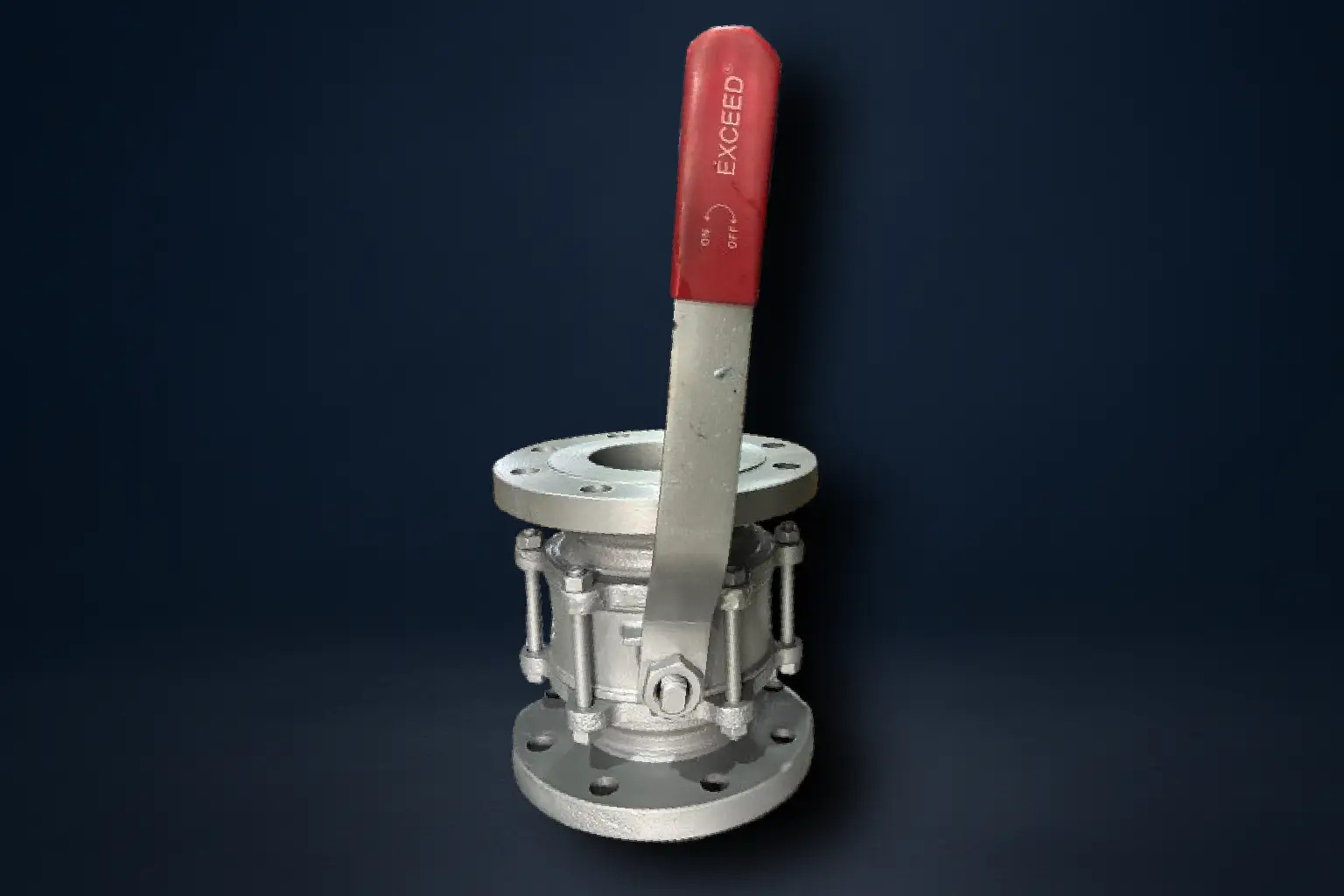
Ball Valves

Service Image

Ball Valves

Ball valves are quarter-turn valves designed for fast and reliable shut-off in fluid systems. They use a spherical disc (the “ball”) with a central hole (bore) that controls flow. When the ball’s bore is aligned with the pipeline, the valve is fully open, allowing unobstructed flow. A simple 90° turn of the handle or actuator rotates the ball, positioning the bore perpendicular to the line and completely stopping flow.

This design provides excellent sealing, minimal pressure drop, and easy operation, making ball valves one of the most widely used valves in industries such as oil & gas, water supply, chemical processing, and power generation. They are especially valued where tight shut-off, frequent operation, and low maintenance are required.

Exceed Ball Valves are built with precision-engineered balls and seats for bubble-tight sealing, smooth operation, and long service life. With robust construction and options for manual, pneumatic, or electric actuation, Exceed ensures reliable performance across demanding applications.


Technical Details:

Construction: 

  • 3 Piece/2 Piece
  • Blowout Proof Stem
  • Floating Ball
  • Soft Seated
  • Full Bore

Manufacturing Std.: BS 5351

Testing & Inspection Std.: API 598

Face to Face: ASME B16.10

End Connections: ASME B16.5 RF


Engineering Options:

  • Available on request with gearbox or pneumatic actuator
  • Speacial materials on request
  • Solid Ball on request
  • Remote operations on request
  • Valve design provides for interchangeability of items
  • Glass filled PTFE Seat on request
  • Sealing materials can be given in grofoil

The operation of a ball valve is based on a quarter-turn mechanism:

  1. Open Position
    When the handle or actuator rotates the ball so that its bore is aligned with the pipeline, fluid flows freely through the valve. The straight-through flow path results in very low pressure drop, preserving system efficiency.

  2. Closed Position
    Rotating the ball 90° moves the bore perpendicular to the pipeline, blocking flow completely. The solid surface of the ball presses against the valve seats, creating a tight seal even under high pressure.

  3. Intermediate Position (Throttling)
    Although ball valves are primarily designed for shut-off, they can be partially opened to regulate flow in some cases. However, extended throttling service may reduce seat life, so they are best used for on/off applications.

Because of this simple design, ball valves are easy to operate, quick to actuate, and reliable in both manual and automated systems.

Ball valves are commonly used:

  • In pipelines requiring tight shut-off – to ensure zero leakage in oil, gas, and chemical transfer lines.

  • At system isolation points – for quick and reliable shut-off during maintenance or emergencies.

  • In utility services – such as water distribution, compressed air, and steam lines, where durability and ease of use are essential.

  • With automation systems – when paired with pneumatic or electric actuators for remote or frequent operation.

  • Tight Sealing
    Ball valves provide bubble-tight shut-off, preventing leakage even in high-pressure systems.
    Exceed uses precision-machined balls and resilient seats to achieve superior sealing performance.

  • Low Pressure Drop
    The straight-through flow path results in minimal resistance and energy loss.
    Exceed designs its valves for maximum flow efficiency and reduced turbulence.

  • Quick Operation
    Only a 90° turn is needed to fully open or close the valve, making it ideal for rapid shut-off.
    Exceed offers smooth-operating stems and actuation options for easy handling and automation.

  • Durable and Versatile
    Ball valves are suitable for a wide range of fluids, pressures, and temperatures.
    Exceed selects high-quality materials and robust construction to ensure long service life in demanding conditions.

  • Automation Ready
    Ball valves are easily adapted to automated control systems.
    Exceed provides ball valves with optional pneumatic or electric actuators for reliable remote operation.

No. Parts Name Qty. Materials
1 End Pieces 2 ASTM A216 Gr. WCB

ASTM A351 Gr. CF8/CF8m

2 Stud/Nuts Req MS ASTM A 193 Gr. B7

MS ASTM 194 Gr. 2H

3 Body 1 ASTM A216 Gr. WCB

ASTM A351 Gr. CF8/CF8M

Ball 1 SS 304
5 Seat 2 PTFE
6 Stem 1 SS 304/316
7 Interlock Nut 1 MS
8 Lever 1 MS


Material Class Working Pressure @ 38°C Temp. Hyd. Test Pressure (Body) Hyd. Test Pressure (Seat)
WCB

150


300

19.6 bar


51.1 bar

110ºC

29.4 bar


76.7 bar

21.6 bar


56.2 bar

CF8/CF8M

150


300

19 bar


49.6 bar

110ºC

28.5 bar


74.4 bar

20.9 bar


54.6 bar

Important Notes:

1) Temprature shown is the maximum service temprature of the valve. The allowable working pressure decreases as temprature increases. Always refer to the ASME B16.34 pressure-temprature ratings for the exact value at the required temprature.

2) Hydrostatic test pressures are based on API 598 requirements:

  • Body (shell) test = 1.5 x rated working pressure
  • Seat (closure) test = 1.1 x rated working pressure
Size NB. A B C D E F G
15 108 35 11 89 4 60 16
20 118 43 13 98 4 70 16
25 127 51 14 108 4 79 16
40 165 73 14 127 4 98 16
50 178 92 16 152 4 121 19
65 190 105 17 178 4 140 19
80 203 127 19 190 4 152 19
100 229 157 24 229 8 190 19
125 254 186 24 254 8 216 22
150 267 216 25 279 8 241 22
200 292 270 29 343 8 298 22

(Dimension above 200mm available on request)

*All dimensions are in mm

Size NB. A B C D E F G
40 191 73 21 156 4 114 22
50 216 92 22 165 8 127 22
65 241 105 25 190 8 149 22
80 282 127 29 209 8 168 22
100 305 157 32 254 8 200 22
125 381 186 35 279 8 235 22
150 403 216 37 318 12 270 22
200 419 270 41 381 12 330 25

(Dimension above 200mm available on request)

*All dimensions are in mm